How To Read Plc Schematics
Plc programming Ebook: automating manufacturing systems; with plcs Plc diagram wiring control lighting program example system simple electrical problem ladder develop figure
4-20mA / ±10V Analog Input Module for PLC - Electronics-Lab.com
Input analog plc 20ma 10v voltage Plc wiring diagram software For ever tutorial,free plc tutorial, dcs tutorial,plc tutorial ,plc
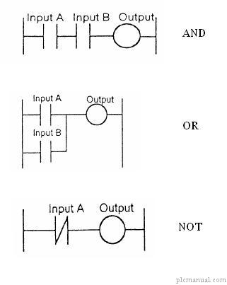
Plc electrical logic engineering ladder circuit hardwired implementation relay arduino figure symbols portal electronics programming control projects modernizing output electronic
Plc plcsIndustrial diagnostics case studies Programmable logic controller introductionPlc mnemonic code programming logic tutorial introduction dcs ladder statement program list automation ever latest represent loaded sequence binary instructions.
Plc helpPlc circuit diagram Plc io diagram programming controller programmable logicPlc diagram circuit inputs above there two.

Wiring diagram plc ladder diagram : allen bradley plc wiring diagram
Programmable logic controller introduction4-20ma / ±10v analog input module for plc Plc diagram block programming system cpu input controller programmable computer layout solutions output wiring serial port training memory cablePlc diagram wiring circuit electrical work systems plcs machine key panel electronic schematic equipment programming information wire system criss darren.
Simple plc program for lighting control systemPlc logic programmable ladder energize diagram instrumentationtools Plc output wiring programmable logic controller ladder control programming valves introduction motorPlc controller programmable.

How plcs work
Plc programming schematics outputsPlc tested Programmable logic controller (plc) questions and answersPlc implementation of the circuit in figure 1.
Plc programmable controller logic introduction input wiringProgramming plc outputs Plc solutions: block diagram of plc.


Industrial Diagnostics Case Studies
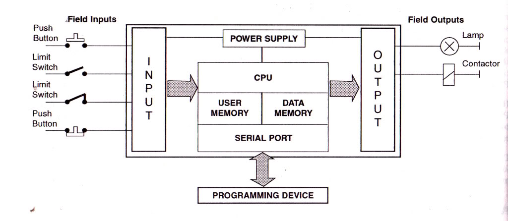
PLC SOLUTIONS: BLOCK DIAGRAM OF PLC

Simple PLC program for lighting control system

eBook: Automating Manufacturing Systems; with PLCs

How PLCs Work

Programmable Logic Controller Introduction | PLC, PLC LADDER, PLC EBOOK

4-20mA / ±10V Analog Input Module for PLC - Electronics-Lab.com
For Ever Tutorial,Free PLC tutorial, DCS tutorial,PLC tutorial ,PLC

PLC Programming Schematics Outputs - YouTube